In this essay we will discuss about the basic types of OTEC plants. Also learn about the best features of open and closed OTEC system.
Essay # 1. Closed Cycle (Anderson Cycle, Vapour Cycle) System:
The closed cycle OTEC concept was proposed by ‘Barjot’ in 1926. The cycle was further developed by ‘Anderson’ in 1992.
All the systems being proposed for construction, now work on “Closed Rankine cycle” (Anderson cycle, vapour cycle) and use low boiling point working fluids like ammonia, propane, freon (R-12, R-22) etc. These systems will be located off-sore on large floating platforms or inside floating hulls.
The warm surface water is used for supplying the heat input in the ‘boiler’, while cold water brought up from ocean depths is used for extracting the heat in the ‘condenser’.
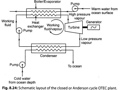
Fig. 8.24 shows a schematic diagram of a closed or Anderson cycle OTEC plant.
Working of Closed Cycle System:
i. Warm water from ocean surface is circulated through a pump to a ‘heat exchanger’ which acts as a ‘boiler’ to generate working fluid ammonia vapour at high pressure.
ii. This vapour expands in the ‘turbine’ to develop mechanical power, which in turn runs an electric ‘generator’ to produce electric power.
iii. The working vapour from turbine at low pressure is condensed in the ‘condenser’ with the help of cold water drawn from the depth of ocean through a pump.
The overall efficiency of such a plant is very low in the range of 2 to 3% only. Inspite of this, the concept of an OTEC system seems to be economically attractive because both the collection and storage of solar energy is being done free by nature.
The “major advantage” of this system is that fluid evaporates at around 25°C and does not require vacuum pumps. The pressure at the turbine will be of the order of 9 to 6 bar resulting in compact turbines (Example: In a 1MW plant, the NH3 turbine will have about 1.1 m diameter which is easy to fabricate technically).
The following points about OTEC are worth noting:
1. Each of the possible working fluids i.e. ammonia and propane has the following advantages and disadvantages:
i. “Ammonia” has better operating characteristics than propane and it is much less inflammable. On the other hand ammonia forms irritating vapour and probably could not be used with copper heat exchanger.
ii. “Propane” is compatible with most heat-exchanger materials, but is highly flammable and forms an explosive mixture with air.
Ammonia has been used as the working fluid in successful tests of the OTEC concept with closed cycle systems.
2. Because of the low cycle efficiency the heat to be transferred in the boiler and condenser is large. In addition, the temperature difference between the sea water and the working fluid in these heat exchangers has to be restricted to very small values. For these reasons, very high flow rates are required for the sea water both in the boiler/evaporator and the condenser. This results in high pumping power requirements and is reflected in the gross power outputs which are 20-50 percent higher than net power outputs.
i. A second important consequence is that both the evaporator and condenser are much larger in size than similar components in conventional practice.
ii. The materials suggested for these heat exchangers are titanium or an alloy of copper and nickel. This is necessitated because of the corrosive nature of the sea water.
3. An examination of the breakup of the OTEC system costs shows that the cost of heat exchangers plays an important role in costing; they contribute about 30 to 40 percent of the total.
Essay # 2. Open Cycle (Claude Cycle, Steam Cycle) System:
In this system, the warm water is converted into ‘steam’ in an evaporator. The steam drives steam-turbine generator to deliver electrical energy.
Fig. 8.25 shows the schematic layout of the open or claude cycle OTEC plant.
The warm water from ocean surface is admitted through a ‘deaerator’ to the ‘flash evaporator’ which is maintained under high vacuum. As a result, low pressure steam is generated due to throttling effect and the remainder warm water is discharged back to the ocean at high depth.
The deaerator also removes the dissolved non-condensable gases from water before supplied to the evaporate.
The low pressure steam having very high specific volume is supplied to ‘turbine’ where it expands and the mechanical power so developed is converted into electric power by the ‘generator’.
The exhaust steam, from turbine is discharged into a direct contact type condenser where it mixes with cold water drawn from ocean at a depth of about 1 to 2 km. The mixture of condensed steam and ocean cold water are discharged into the ocean.
Advantages of Open Cycle System:
1. The warm Ocean water is flash evaporated and the need for having a surface heat exchanger is eliminated.
2. The portable water is obtained when the exhaust steam from the turbine is condensed.
Disadvantages of Open Cycle System:
1. As the steam is generated at very low pressure (0.02 bar approx.) the volume of steam to be handled is very large, leading to a very large diameter for the steam turbine. (Example- A 1 MW OTEC plant requires a steam turbine of 12 m in diameter.)
2. To maintain the vacuum in the flash evaporator, massive vacuum pumps will be required.
3. The plant cost is high.
4. The plant is subjected to extremely reverse stresses.
Modified Open Cycle OTEC Plant:
The efficiency of the open cycle OTEC plant can be increased by making the following modifications:
1. Improved evaporator called controlled flash-steam evaporator.
2. Use of surface condenser instead of direct contact condenser.
3. Use of plant for cogeneration of electric power and fresh water.
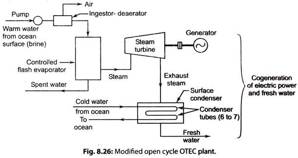
Fig. 8.26 illustrates a modified open cycle OTEC, “Cogeneration plant” which generates electric power and fresh water.
Working of Open Cycle System:
i. Warm ocean water is fed into the controlled flash evaporator via the ingestor-deaerator.
ii. Steam collected from flash steam evaporator is supplied to the steam turbine. Spent water from the evaporator is returned to the ocean.
iii. Steam turbine drives the electric generator and delivers power to the network.
iv. Exhaust steam from the steam turbine is condensed in ‘surface condenser’ and ‘fresh water’ is supplied to users.
v. As the plant supplies electric power and fresh water, it is a “cogeneration plant”.
vi. Cold water from condenser is drawn from deep ocean and after circulating through the condenser tubes the spent water is discharged into the ocean.
Essay # 3. Best Features of Open and Closed System:
I. Hybrid OTEC System:
This system combines the best features and avoids the worst features of the open and close cycle systems.
Working:
i. The warm ocean water is flash evaporated to steam, as in open cycle.
ii. The heat is then transferred to ammonia based closed Rankine cycle system.
iii. The ammonia gas is then fed to the turbine, which is coupled to the generator to generate electricity.
iv. The ammonia goes to condenser unit and finally pumped to evaporator to repeat the cycle.
II. Thermoelectric OTEC System:
This OTEC system was developed by Solar Energy Research Institute Colorado USA, during 1979.
It operates on the “thermoelectric principle” which is simple in construction and economical.
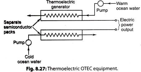
Fig. 8.27. shows a thermoelectric OTEC equipment. It consists of two separate packs, made of semiconductors, and covered by a thin thermal conducting sheet.
Working:
i. The warm water from the surface of ocean is circulated over one device and cold water pumped from the depth of ocean is allowed to flow over other device.
ii. The temperature difference of two waters with the solid state semiconductor devices generate the electric power using thermoelectric effect. The economy of the OTEC depends on large variation of water temperature used for the surface and the deep ocean (minimum 20°C).
Bio-Fouling:
Bio-fouling (the deposition and growth of micro-organisms) is the biological impurity of sea water that deposits and grows on evaporator and condenser metal surfaces, creating thermal resistance for heat transfer.
The total formulation of bio-fouling, corrosion and so on is referred to a fouling (or scaling) and will tend to inhibit heat transfer through it.
The fouling factor is a measure of the thermal resistance of a fouling film. Provisions must be made to inhibit the formation of fouling layers on the surfaces of OTEC heat exchangers etc. This can be accomplished by periodically cleaning the heat exchanger surfaces through mechanical, chemical or other means.


