Are you looking for an essay on the ‘Applications of Solar Energy’? Find paragraphs, long and short essays on the ‘Applications of Solar Energy’ especially written for school and college students.
Applications of Solar Energy
Essay Contents:
- Essay on Solar Water Heating
- Essay on Space Heating (or Solar Heating of Buildings)
- Essay on Space Cooling (or Solar Cooling of Buildings)
- Essay on Solar Distillation (Solar Still)
- Essay on Solar Pumping
- Essay on Solar Air Heaters and Drying
- Essay on Solar Cooking
- Essay on Solar Furnace
- Essay on Solar Green-Houses and Global Warming
- Essay on Solar Power Plants
- Essay on Silicon Cell Modules
- Essay on Photovoltaic (PV) Systems
1. Essay on Solar Water Heating:
Solar water heating is one of the most common applications of solar energy.
a. Natural Circulation Solar Water Heater:
A natural circulation solar water is usually used in most “domestic systems”.
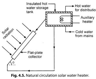
A simple solar water heater with natural circulation is shown in Fig. 4.5.
Construction of Natural Circulation Solar Water Heater:
It consists of a flat- plate solar collector, normally single glazed, and insulated storage tank kept at a height. It is installed on a roof with the collector facing the sun and connected to cold water mains. The collector comprises copper tubes welded to a copper sheet (both coated with a highly absorbing black coating) with a toughened glass sheet on top and insulating material on the rear. Fig. 4.5. Natural circulation solar water heater.
Working of Natural Circulation Solar Water Heater:
The collector collects the sun radiation due to which water flowing through the tubes absorbs solar heat and is stored in a tank. The water circulation is entirely based on the density difference between the solar-heated water in the collector and the cold water in the storage tank. Hot water for use is taken out from the top of the tank.
To provide heat during long, cloudy periods, an electrical immersion heater (i.e. ‘auxiliary heater’) can be used as a back-up for the solar system. A non-freezing fluid may be used in the collector circuit.
Most domestic systems are of capacity ranging from 100 to 150 litres of hot water per day.
b. Forced-Circulation Solar Water Heater:
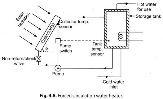
Solar water heaters of this type which are suited to supply large quantity of hot water, are suitable for industries, hospitals, hostels and offices. Fig. 4.6. shows a forced- circulation solar water heater with a pump. Water is pumped through flat-plate solar collector(s) where it is heated and flows back into the storage tank.
Whenever hot water is withdrawn for use, cold water takes its place. When the difference in water temperature at the collector(s) outlet and that at the storage tank exceeds 7°C, the pump motor is activated by a differential thermostate. A non-return/check valve is needed to prevent reverse circulation and resultant night time thermal losses from the collector.
2. Essay on Space Heating (or Solar Heating of Buildings):
All solar heating systems may be divided into the following two categories:
i. Active Systems:
These systems generally consist of the following components:
(i) Separate solar collectors, which may heat either water or air,
(ii) Storage devices which can accumulate the collected energy for use at nights and during inclement days, and
(iii) A back-up system to provide heat for protracted periods of bad weather.
ii. Passive Systems:
In such systems solar radiation is collected by some element of structure itself, or admitted directly into building through large, south facing windows.
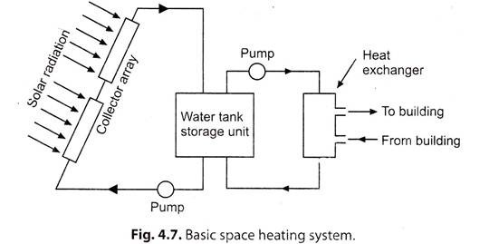
Fig. 4.7. shows a basic space heating system.
The collector array collect the solar radiation and heat up the water. This heated water is stored in the tank and the energy is transferred to the air circulating in the building by water to air heat exchanger. Tow pumps are provided for forced circulation between the collectors and the tank, and between the tank and heat exchanger.
Limitations of Uses of Solar Water Heating System:
1. The energy received from the sun in cloudy days is almost nil and so the output of solar collector^) will be almost zero and hence the system cannot provide the necessary service required.
2. For the functioning of the system, it is necessary to have continuous cold water supply at a height of around 2.5 m.
3. The insulation of the tank must be good, to ensure availability of ‘heated water during the day’ for use during night and next morning.
4. Owing to the deposit of hard water scale in the collector, the efficiency of the system is likely to reduce.
5. Sometimes hot water supply may stop due to vapour locking in pipeline.
3. Essay on Space Cooling (or Solar Cooling of Buildings):
Solar energy can be used in air-conditioning and refrigeration. The principles of the following two cycles are used for refrigeration using solar energy.
1. Absorption cycle
2. Vapour compression cycle
i. Absorption Cycle:
In this cycle, two working fluids are used:
(i) A refrigerant, and
(ii) Absorbent-refrigerant solution.
The absorbent cooling is based on the principle that the refrigerant can be bound by a liquid or solid solvent, known as absorbent to release heat during operation, while it absorbs heat during evaporation, thus producing a “cooling effect.”
Common refrigerant-absorbent combinations are:
(i) Lithium bromide (Li) – Water (LiBr-H2O).
(ii) Ammonia-water (NH3-H2O).
a. “LiBr-H2O system” is simple and requires lower generator temperature of the order of 85°C to 95°C which are achievable by a flat-plate collector. Also it possesses higher C.O.P. than the NH3-H2O system
b. Absorption cooling with solar energy, which is regarded as more practical, is possible with current technology although improvement in design would be desirable.
ii. Vapour Compression Cycle:
In this cycle, shaft power produced by solar power conversion into mechanical power by “heat pump” is used to drive compressor of refrigerator. Compressed vapour is then “condensed” to a liquid rejecting it through an “expansion valve” where it gets “evaporated” at low pressure, producing a cooling effect.
Liquid refrigerants are: LiBr-H2O; NH3-H2O; NH3-LiNO3 etc.
Solid absorbents are: CaCl2-NH3; Silica gel-H2O; Zeolite-H2O etc.
Vapour Absorption Cooling System:
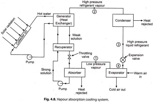
Refer to Fig. 4.8. A vapour absorption cooling system consists of the following components:
(i) Generator (or Heat Exchanger);
(ii) Condenser;
(iii) Evaporator;
(iv) Absorber.
Working of the System:
i. The low pressure refrigerant vapour leaving the evaporator at ‘V is readily absorbed in the low temperature hot solution in the absorber, releasing the latent heat of condensation. The temperature of the solution tends to rise, while the absorber is cooled by the circulating water, absorbing the heat of solution, and maintaining a constant temperature.
ii. Strong solution, rich in refrigerant, is pumped (pump increases the pressure of the solution) to the generator where heat is supplied by the collector array. The high pressure refrigerant vapour is given off, and the weak solution returns to the absorber through throttling (or pressure reducing) valve.
iii. The high pressure refrigerant vapour from the generator at ‘2’ is condensed in the condenser to a high pressure liquid at ‘3’ refrigerant.
iv. The liquid refrigerant is throttled by the expansion valve at ‘4’, and then evaporates, absorbing the heat of evaporation from the warm air or surroundings.
Advantages:
This system claims the following advantages over vapour compression cycle:
1. No moving part in the system except the pump-motor.
2. Quiet in operation, very little wear, and low maintenance cost.
3. More compact and less bulky.
4. The space requirements and automatic control requirements favour the absorption system more and more as the desired evaporator temperature drops.
4. Essay on Solar Distillation (Solar Still):
Solar still is a device which is used to convert saline water into pure water by using solar energy.
Soft drinking water, an essential requirement for supporting life, is scarce in arid, semi-arid and coastal areas. Saline water, at such places, is available in underground or in the ocean. This water can be distilled utilising abundant solar radiation available in that area, by solar still(s).
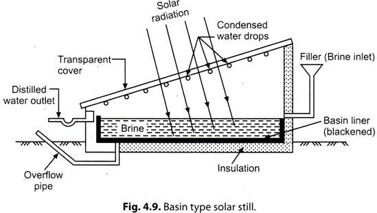
The simplest ‘solar still’, generally known as, ‘basin type solar still’ is shown in Fig. 4.9.
Construction:
It is a shallow basin having blackened surface called basin liner. The filler supplies the saline water to the basin and an overflow pipe allows the excess water to flow out from the basin. The top of the basin is covered with a sloping airtight transparent cover that encloses the space above the basin. This cover is made of glass or plastic and slope is provided towards a collection trough.
Working:
Solar radiation passes through the transparent cover and is absorbed and converted into heat by the black surface of the still. The saline water is then heated and the water vapours condense over the cool interior surface of the transparent cover. The condensate flows down the sloping roof and gets collected in troughs installed at the outer frame of the solar still. The distilled water is then transferred into a storage tank.
“Desalination output” increases with the rise in ambient temperature and is independent of the salt content in raw feed water.
The “solar still performance” is expressed as the quantity of water produced by each unit of basin area per day.
Solar still installations may provide about 15 to 50 litres/day/10 m2.
Advantages of Distilling Process:
1. Low energy consumption.
2. Less skilled labour required.
3. Simple technique required.
4. Low maintenance cost.
5. Essay on Solar Pumping:
Solar pumping utilises the power generated by solar energy for water pumping, useful for irrigation. Water pumps can be driven directly by solar heated water or fluid which operates either a heat engine or turbine.
For low heads, a flat-plate collector is used to heat a low-boiling point liquid, the vapour of which drives the pump. For larger heads, a parabolic trough concentrator or parabolic bowl concentrator is installed to drive a steam turbine, which in turn drives the pump.
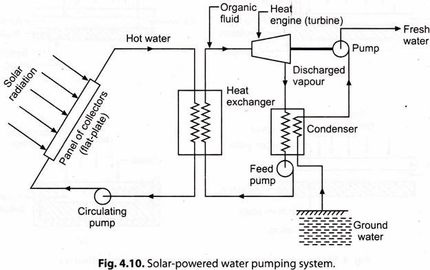
Fig. 4.10 shows a typical solar-powered water pumping system.
Working of Solar Pumping:
The panel of solar flat-plate ‘collectors’, on receiving solar radiation, heat water or an organic fluid (R-115 is an acceptable working fluid as it has low cost and high cycle efficiency).
i. The hot fluid then flows to a mixing/ storage tank and then to a heat exchanger to convert the working fluid of the heat engine from liquid to vapour.
ii. Water or hot transport fluid is fed again into the collector circuit by a ‘circulating pump’
iii. The discharged vapour, from the turbine, flows into ‘condenser’ where the vapour gets condensed. The working fluid is then fed into the heat exchanger by a ‘feed pump’ to complete the cycle. The water, which is pumped, is used as a coolant in condenser of the turbine.
A high engine efficiency is achieved if the temperature in heat exchanger or boiler is high.
6. Essay on Solar Air Heaters and Drying:
Solar Air Heaters:
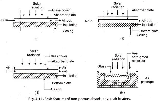
A conventional solar air heater is essentially a flate-plate collector with an ‘absorber plate’, a ‘transparent cover, system’ at the top and ‘insulation’ at the bottom and on the sides. The whole assembly is encased in a sheet metal container. The working fluid is “air”, though the passage for its flow varies according to the type of air heater.
The ‘materials’ used for construction of air heaters are similar to those of liquid flat-plate collectors. ‘Selective coating’ on the absorber plate can be used to improve the collection efficiency but cost effectiveness criterion should be kept in mind.
Figs. 4.11 [(f) to (iv)] shows the basic features of non-porous absorber type air heaters.
Advantages of Solar Air Heaters:
The solar air heaters claim the following advantages over other solar heat collectors:
1. The system is compact and less complicated.
2. The pressure inside the collector does not become very high.
3. Leakage of air from the duct does not pose any major problem.
4. Corrosion is completely eliminated.
5. Freezing of working fluid does not exist.
Disadvantages of Solar Air Heaters:
1. Poor heat transfer properties.
2. Need for handling large volumes of air.
3. The thermal capacity of air being low, it cannot be used as a storage fluid.
4. In the absence of proper design, the cost of air heater can be very high.
Important Areas of Applications:
The important areas of applications of non-porous absorber type air heaters are:
1. Heating and cooling buildings (such heaters are used only in actively heated or cooled buildings).
2. Air heaters are also used as desiccant beds for solar air-conditioning.
3. Heating of green-house.
4. Industrial processes such as drying agricultural crops and timber.
Solar Drying:
Drying has been the oldest and most widely used application of solar energy in the developing countries. The methods have been based on open air drying.
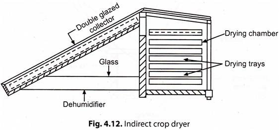
Fig. 4.12. shows the schematic diagram of an indirect crop dryer (Headly and Springer design).
In this type of dryer, ambient air is heated and is passed into drying chamber by natural convection. The hot air removes moisture from the crops, becomes cooler and falls to the bottom of drying chamber. By this system, yam, sweet potato, sorrel and grasses can be dried.
For large scale drying, i.e. seasoning of timber, corn drying, tea processing, tobacco curing, fish and fruit drying, solar kins are used.
Advantages of Solar Drying:
1. Dried products improve family nutrition (Dried fruit and vegetables contain high quantities of vitamins, minerals and fibre.
2. Dried fruit can be used in stews, soups, making ice-cream and baked products.
3. Improves the bargaining position of farmers. Disadvantages:
1. The dried product is often of poor quality as a result of grit and dirt.
2. The product is often unhygienic as a result of microorganism and insects.
7. Essay on Solar Cooking:
In India, cooking is the common application of solar energy. Several varieties of solar cookers are available to suit different requirements.
Following types of cookers will be briefly discussed:
1. Box-type solar cooker.
2. Dish solar cooker.
3. Community solar cooker for indoor cooking.
1. Box-Type Solar Cooker:
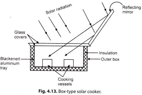
Fig. 4.13 shows a box-type solar cooker.
It consists of an ‘outer box’ made of either fibre glass or aluminium sheet, a ‘blackened aluminium tray’, a ‘doubleglass lid’, a ‘reflector’, ‘insulation’ and ‘cooking pots’. The blackened aluminium tray is fixed inside the box, and the sides are covered with an insulation cover to prevent heat loss. The reflecting mirror provided on the box cover increases the solar energy input. Metal pots are painted black on the outside.
Food to be cooked is placed in cooking pots and cooker is kept facing the sun to cook the food. An electric heater may also be installed to serve as a back during non-shine hours.
Technical Drawbacks of the Design:
The Government of India is trying to introduce box-type solar cookers with financial subsidies but with poor success due to the following technical drawbacks of the design of the box-type solar cooler:
1. The temperature obtained is less than 100°C and is insufficient for chapati making and frying which are very important cooking processes.
2. There is no provision for storage of heat and cooking gas to be carried out while the sun is shining, which is an odd time for preparing breakfast and dinner.
3. Cooking has to be carried out in open without privacy and in the sun which is very inconvenient to housewife.
2. Dish Solar Cooker:
In this type of cooker, a ‘parabolic dish’ is used to concentrate the incident solar radiation. A typical dish solar cooker has an aperture of diameter 1.4 m with focal length of 0.8 m. The ‘reflecting material’ is an anodized aluminium sheet having reflectivity of over 80%.
The cooker needs to track the sun (which requires power of about 0.6 kW). The temperature at the bottom of the vessel may reach up to 400°C which is sufficient for boiling, roasting and frying.
Such a cooker can meet the requirements of cooking for fifteen persons.
3. Community Solar Cooker for Indoor Cooking:
A community solar cooker is a ‘parabolic reflector cooker’. It has a ‘large reflector’ ranging from 7 to 12 m2 of aperture area. The reflector is placed outside the kitchen so as to reflect solar rays into the kitchen. A ‘secondary reflector’ further concentrates the rays on to the bottom of the cooking pot painted black. Temperature can reach up to 400°C and food can be cooked quickly for fifty persons.
Essay # 8. Solar Furnace:
A solar furnace is an optical equipment to get high temperatures by concentrating solar radiations on to a specimen.
The “primary components” of a solar furnace are:
1. Concentrator:
In solar furnaces, either a paraboloidal reflection concentrator or a spherical reflector concentrator is used; the former is considered superior due to acceptable spherical aberration in a spherical reflector.
2. Heliostat:
In a solar furnace, the function of heliostats is to orient solar radiation parallel to the optical axis of the concentrator. As a guide, the size of the heliostat should be 1.4 D x 1.4 D where D represents the size of aperture of concentrator.
3. Sun Tracking:
For a solar furnace to function with optimum output, it is imperative that heliostats should follow the sun from morning till evening.
In a solar furnace the temperatures may reach up to 3500°C.
Solar Furnace with Multiple Heliostat:
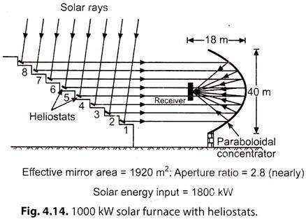
The world’s first 1000 kW solar furnace was operated at Odeillo, France, in 1973. Solar intensity was 1 kW/m2, with bright sunshine for about 1200 hours a year. It consisted of 63 heliostats installed at 8 elevations which reflected sun rays to the concentrator parallel to its optical axis as shown in Fig. 4.14. The receiver diameter was changed to obtain different temperatures.
Advantages of Solar Furnace:
1. Simple working.
2. High heat flux is obtainable.
3. Heating without contamination.
4. Easy control of temperature.
Uses of Solar Furnace:
1. For phase and vaporisation studies.
2. Melting behaviour analysis.
3. Purification of ceramic and refractory materials.
Essay # 9. Solar Green-Houses and Global Warming:
Solar Green-Houses:
A green-house is an enclosed space which provides the required environment for growth and production of plants under adverse climatic conditions. Its design depends upon the local climatic conditions and the environment needed for the growth.
Plants manufacture their food by ‘photosynthesis process’ which maintains a balance with respiration.
The various parameters for a plant growth are:
1. Light Intersity:
For plant growth a minimum intensity of 25,000 lux is adequate. A green-house structure, with two glaziings can have maximum light intensity up to 50,000 lux on a clear day.
2. Temperature:
Temperature is an important environmental factor for plant growth. For winter crops, the ideal temperature range is from 5° C to 15° C with a variation up to 3° C. For summer crops, the range is from 20° C to 30° C with a variation of 5° C.
The soil temperature of 20° C to 25° C, for most plants, has been reported to be optimum.
3. Humidity:
For plant growth, relative humidity (RH) of air between 30 and 70% is good. Saplings and germinating seeds need high humidity 100% but its value (RH) reduces after they have grown.
4. Air Movement:
It influences transpiration, evaporation of water from soil, availability of CO2 etc. The movement of air at a speed of 0.8 to 2 cm/s is adequate for optimum growth of the plant.
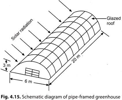
Fig. 4.15 shows a schematic diagram of a pipe-framed green-house.
Advantages of Green-Houses:
This type of structure is less expensive to build than a fully insulated structure.
It provides the following advantages:
1. Inexpensive, good quality food can be grown.
2. An additional heat source (temperature control) is available for the house attached to it.
3. A source of moderator for the humidity (humidity control) in the house.
Global Warming:
Global warming is the term which indicates the increase in the average temperature of the atmosphere. The increased volume of CO2 and other green-house gases released by the burning of fossil fuels and other human activities contribute to the warming of the earth. The amount of heat trapped in the atmosphere depends mostly on the concentrations of greenhouse gases.
The major green-house gases are:
Carbon dioxide,
ozone,
methane,
chlorofluorocarbons (CFCs) and
water vapours.
Due to anthropogenic activities, there is an increase in the concentration of the green-house gases in the air, which results in the increase in average surface temperature.
Deterimental Effects:
1. If the emission of green-house gases continues, the global temperature will increase.
2. With the increase in global temperature sea water will expand, which will result in rise in sea level. Heating will melt the polar ice caps resulting in further rise in sea level.
3. Results in floods.
4. Global warming will lead to changes in the rainfall pattern.
Control Measures:
1. Use of renewable energy sources.
2. Afforestation.
3. Stabilization of population growth.
4. To cut down the current rate of use of CFCs and fossil fuels.
10. Essay on Solar Power Plants:
The solar thermal power generation involves the collection of solar heat which is utilised to increase the temperature of a fluid in a turbine operating on a cycle such as Rankine or Brayton. In another method, hot fluid is allowed to pass through a heat exchanger to evaporate a working fluid that operates a turbine coupled with a generator. These may be classified as: Low temperature, medium temperature and high temperature systems.
Low Temperature Solar Power Plant:
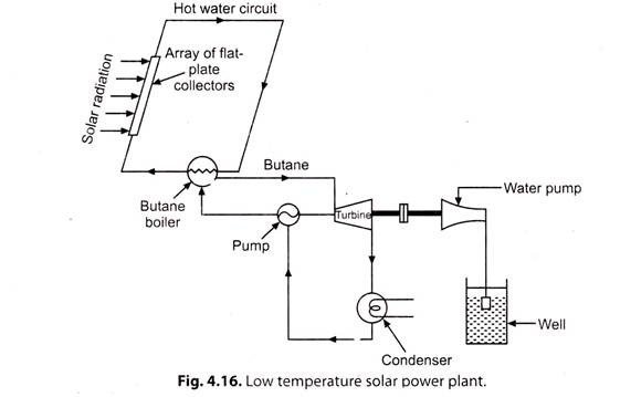
Fig. 4.16. shows a schematic diagram of a low temperature solar power plant.
In this system an array of flat-plate collectors is used to heat water to about 70°C and then this heat is used to boil butane in a heat exchanger. The high pressure butane vapour thus obtained runs a butane turbine which in turn operates a hydraidic pump. The pump pumps the water from a well which is used for irrigation purposes. The exhaust butane vapour (from butane turbine) is condensed with the help of water which is pumped by the pump and the condensate is returned to the heat exchanger (or boiler).
Medium Temperature Systems Using Focusing Collectors:
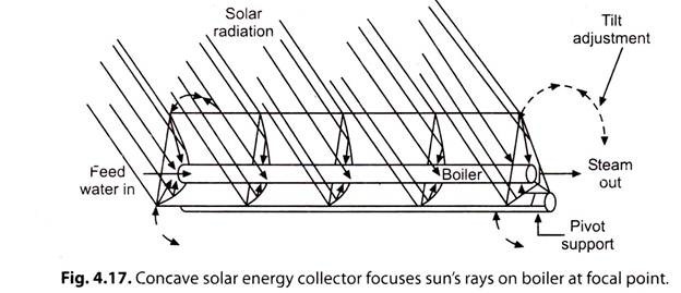
A circular or rectangular parabolic mirror can collect the radiation and focus it on to a small area, a mechanism for moving the collector to follow the sun being necessary. Such devices are used for metallurgical research where high purity and high temperatures are essential, an example being a 55 m diameter collector giving about 1 MW (th) at Mont Louis in Pyrenees. Smaller units having 20 m diameter reflector can give temperatures of about 300°C over an area of about 50 m2. The collector efficiency is about 50%. On a small scale, units about 1 m diameter giving temperatures of about 300°C have been used for cooking purposes.
Fig. 4.17 shows a concave solar energy collector focusing sun’s rays on boiler at a focal point. Generation of steam at 250°C could give turbine efficiencies up to 20-25 per cent.
High Temperature Systems—Solar Farm and Solar Power Plant:
For a large scale production of process-heat the following two concepts are available:
1. The Solar Farm:
It consists of a whole field covered with parabolic trough concentrators.
2. The Solar Tower:
It consists of a central receiver on a tower and a whole field of tracking.
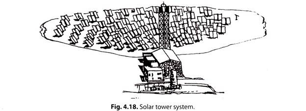
In case of a ‘solar farm’ temperature at the point of focus can reach several hundred degrees Celsius. Fig. 4.18 shows a solar tower system.
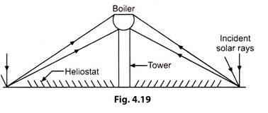
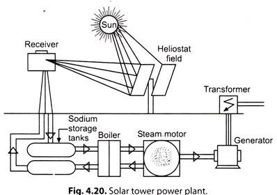
In case of central receiver “solar tower” concentrators, temperature can reach thousands of degrees Celsius, since a field of reflectors (heliostats) are arranged separately on sun- tracking frames to reflect the sun on to a boiler mounted on a central tower (Figs. 4.19, 4.20).
With both systems (‘solar farm’ and ‘solar tower’), a heat transfer fluid or gas is passed through the point or line of insolation concentration to collect the heat and transfer it to the point of use. Such heat can be used either directly in industrial or commercial processes or indirectly in electricity production via steam and a turbine.
The solar technologies such as the above two systems that produce very hot water or steam are currently still under development and, in general, these technologies are not cost competitive with conventional power sources such as oil or gas.
11. Essay on Silicon Cell Modules:
i. ‘Solar cells’ are electrically connected in series and parallel to give suitable voltages and currents for a particular application. A number of cells are generally encapsulated into a module, which is the building block of a photovoltaic system.
a. A typical module measures about 1000 mm x 300 mm x 50 mm and contains 36 cells, which produce 30-35 W at 12 V in bright sunshine.
Several modules combine to form a ‘photovoltaic array’. Galvanized steel, aluminium or chemically treated wood have been used to support the modules, although the latter is not recommended in developing country environments. Arrays are usually fixed in position on concrete foundations.
b. Arrays that can track the apparent motion of the sun and intercept more energy are naturally more expensive and complex.
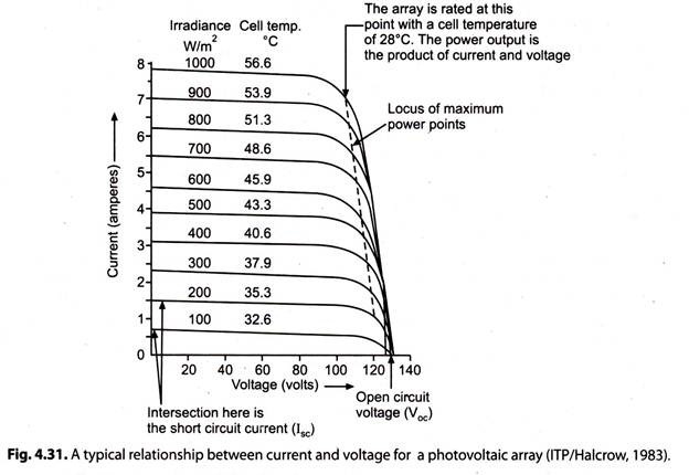
ii. “Photovoltaic modules” are rated in peak watts (Wpk), which refer to the maximum power output from the module when operating at a cell temperature of 28°C (or sometimes 25°C) under a solar irradiance of 1000 W/m2. It is a higher output than that usually achieved in the field.
a. If the cell efficiency is 10%, a 1-kWpk array would contain a cell area of 10 m2. Typically, the packing factor (the ratio of cell area to array area) is about 75%, giving a gross area of 13.3 m2 for a 1-kWpk array.
b. The efficiency and, consequently, the power output of the cell depends on the electrical load because of the relationship between current and voltage for the cells (Fig. 4.31).
c. The efficiency of solar cells falls off about 0.5 percent /°C as the operating temperature rises.
12. Essay on Photovoltaic (PV) Systems:
Solar photovoltaic systems refer to a wide variety of solar electricity systems. Such a system uses solar array made of silicon to convert sunlight into electricity. Components other than PV array are collectively known as ‘balance of system (BOS)’ which includes storage batteries, an electronic charge controller and an inverter.
These systems are of the following two types:
1. Stand-Alone Power Systems:
In such a system, the photovoltaic array is the principal or only source of energy. Energy is stored, often in batteries, for periods when there is insufficient solar radiation. There may also be a back-up power supply such as an engine-generator set.
2. Grid Connected Power Systems:
In this type of system, load is connected to both a photovoltaic power system and an electricity grid. In periods when there is sufficient solar radiation, the array powers the load, otherwise grid is used. In some cases, any surplus electricity produced by the array (i.e. when the load output exceeds the load) is fed back into the grid. This type includes large MW-sized systems.
Stand-Alone Power Systems:
A photovoltaic system can be designed to meet any electrical load. The principal components of stand-alone photovoltaic systems are shown in Fig. 4.32.
Photovoltaic Array:
It consists of the required number of modules interconnected in series and parallel to give the desired system voltage and current.
Storage Battery:
The battery supplies energy to the load during periods of little or no solar irradiance and stores energy from the array during periods of high irradiance. This enables the systems to meet momentary peak power demands and to maintain stable voltage to the load.
Power Conditioner:
Because the voltage output of the photovoltaic array varies with insolation and temperature, systems with battery storage require voltage or shunt regulator to prevent excessive overcharging of the battery. Further controls are used, as required, to prevent discharge or to ensure that the array is operating at its maximum power point.
To determine the capacity and size of a photovoltaic system, it is necessary to select an optimum combination of battery capacity and array size for a particular location. Methodologies for sizing systems are relatively well-developed and employ an hour-by-hour computer model of the system under consideration. The annual energy output from the system can then be calculated for a range of array sizes and battery capacities to select an optimum combination, i.e., the one with the lowest cost.
Standards for Solar Photovoltaic Systems:
Bureau of Indian Standards (BIS) has established photovoltaic standards in India.
i. For electrical safety and system reliability, PV devices need to conform to IS- 12839 (1989) regulation regarding photovoltaic parts.
ii. Measurement of current and voltage is covered by IS-12762 (1989) and IS-12763 (1989) which deal with electrical characteristics of crystalline silicon cells.
Advantages of Photovoltaic Systems:
1. Systems are durable.
2. No operational cost.
3. Low maintenance.
4. More flexibility available.
5. Systems are eco-friendly.
6. Highly reliable.
7. Long effective life.
8. Absence of moving parts.
9. Can function unattended for long periods.
10. High power to weight ratio.
Limitations of Photovoltaic Systems:
1. Weather dependent.
2. Low efficiency
3. High installation cost.
Applications of Photovoltaic (PV) Systems:
The applications of photovoltaic systems are:
1. Solar street lighting system.
2. Home lighting systems.
3. Water pumping systems (for micro irrigation and drinking water supply).
4. Solar vehicles.
5. Radio beacons for ship navigation at ports.
6. Community radio and television sets.
7. Cathodic protection of oil pipelines.
8. Railway signalling equipment.
9. Weather monitoring.
10. Battery charging
Water Pumping Systems:
The photovoltaic water pumping systems (major application of PV systems) essentially consist of:
(i) A photovoltaic (PV) array,
(ii) Storage battery,
(iii) Power control equipment,
(iv) Motor pump sets, and
(v) Water storage tank.
Solar Pump Configurations:
Because the batteries have several disadvantages (e.g. power loss, increased risk of failure, shorter operational life than the rest of the solar pump and regular maintenance requirement), at present, most solar pumping systems do not include batteries, although where water storage is needed, a viable alternative may be provided.
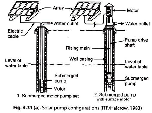
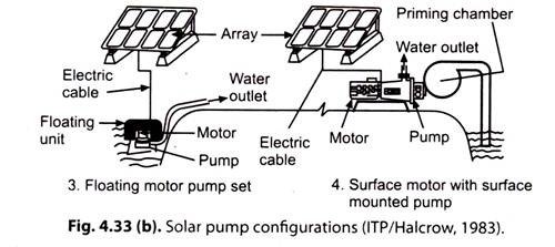
The four principal combinations of motor and pump that are suitable for solar pump are:
1. Submerged motor pump set;
2. Submerged pump with surface motor;
3. Floating motor-pump set;
4. Surface motor with surface mounted pump.
These combinations are shown in Fig. 4.33.
SPV Lighting System:
Solar street light, as shown in Fig. 4.33, describes a stand-alone PV power generating device.
SPV lighting system has the following advantages:
1. Compact in size.
2. Highly durable.
3. Highly efficient.
4. Low maintenance.
PV Hybrid System:
A dedicated PV system cannot give continuous supply even with the use of the storage batteries. The stand-alone PV systems are not reliable during the periods when the solar incidence is low and days and nights are cloudy.
In order to meet with these difficulties, a “hybrid system” has been evolved to meet the load requirements regularly.
A PV system with a diesel generator along with batteries was installed in 1987 in an island isolated from main power grid. A 100 kW solar cell module and the associated devices including the power conditioner was supplied by M/s. Hitachi.
This design has the following two features:
(i) Stand-alone operation mode;
(ii) A parallel operation mode with a diesel unit; an additional diesel generator can also be added in the system.
